Jaguar TCS Racing
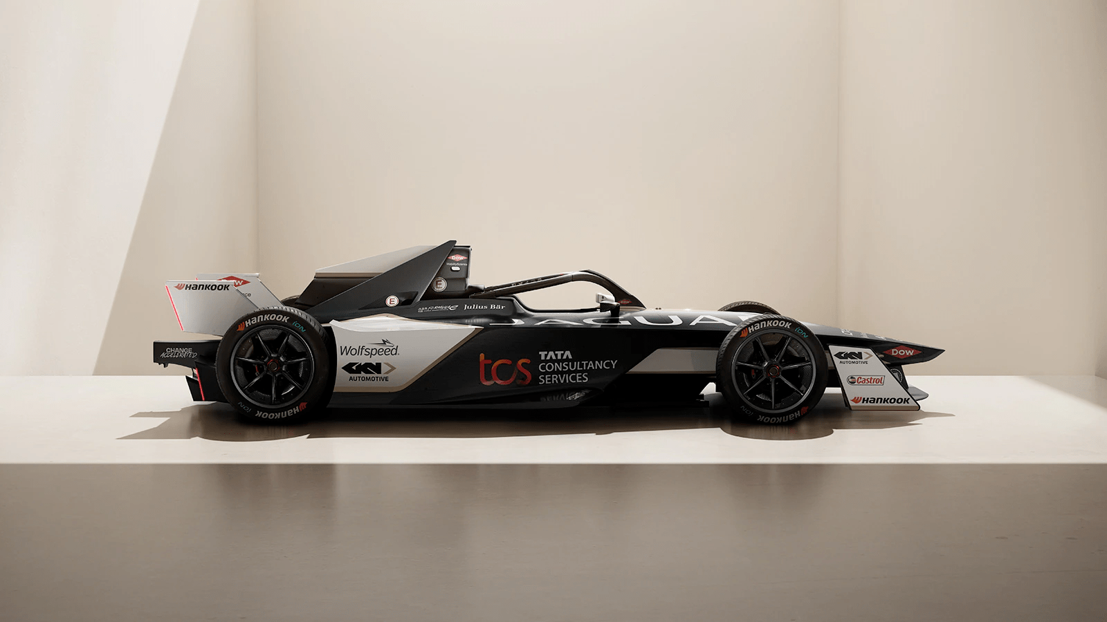
For the Season 9 ABB FIA Formula E World Championship, I was on Jaguar TCS Racing's performance team as a software developer.
During this time I developed a bespoke real-time mulitplayer race simulation tool and worked on other strategy software that was crucial in understanding how to win races in the new Gen 3 era of Formula E.
I wrote the back-end (in Node.js and Python) and front-end (in Angular) for various projects, as well as helping with the cloud architecture to ensure successful deployment of our tools.
I also trained an image classification neural network model to analyze broadcast footage during race weeekends and assisted the track-side race team with competitor information.

‣
‣
Onboard Charger Wake-Up Circuit
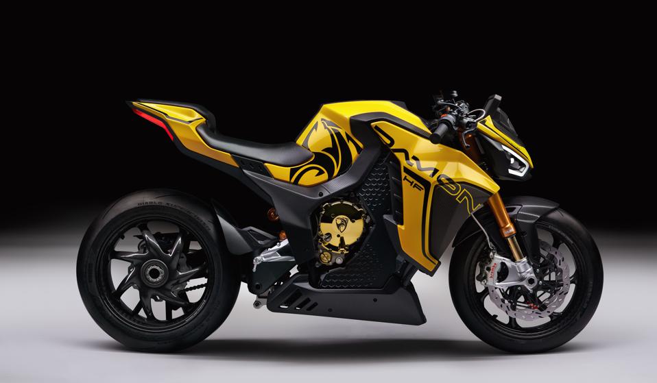
Designed wake up circuit for onboard chargers on Damon Motorcycles.
Circuit Operation
Circuit monitors the CP signal from a standard SAE J1772 compliant charger and draws virtually no power. Once the CP signal begins square wave operation, the wake up circuit then wakes up the rest of the onboard charger.Design Technology
Simulated using LTSpice, then Altium to layout circuit and PCB design, then assembled by hand and tested operation with oscilloscope.
‣
‣
License Plate Detection Robot Controller
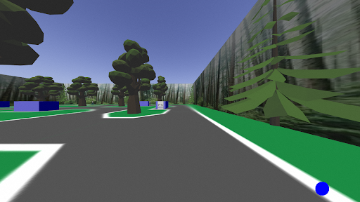
With a partner, designed software to control a virtual robot inside a simulated world to self-drive and auto-detect license plates on parked cars. Project was for a competition for the ENPH 353 course, with 22 other teams participating. Finished 1st in competition, with a perfect score and half the time elapsed of the 2nd place team.
Detection
- Used TensorFlow to create a model for license plate detection; trained with over 10000 generated images of license plates, with noise algorithmically added.
- Read license plates with 99% accuracy and auto submitted them to scoring server.
Driving
- Robot always remained within the road lines and avoided crossing pedestrians and moving cars.
- Robot traversed entire virtual block and approached all eight cars in 41 seconds, without breaking any of the aformentioned rules.
- For most of the navigation, OpenCV was used to find the white road lines and PID controls were utilized to keep robot in the middle of the road.
- Pedestrian and car detection done by comparing past images and comparing pixels for movement.
- For stable cornering, a gradient braking algorithm was developed to ease into deceleration.

‣
‣
Autonomous Can Collecting Robot
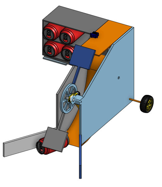
Collaborated in a team of 4 to design and build an autonomous can collection robot. In the final ENPH253 competition, our robot went undefeated in head-to-head matchups and topped our division. Successfully scored 61% more points than the average robot.
Robot Behaviour
- The robot descends from a skycrane, and then follows a tape path to sweep the area for cans.
- The robot uses a water wheel to collect cans into a staging area, where a servo flap then rolls the can into either the lower or upper storage zone.
- The storage wing has a counterweight on its opposite side that biases the storage zone to tip forward.
- Once the robot is done with the path, it initiates the dumping procedure, the storage wing tips over and the cans are placed in their correct slot.
Technology
- Robot was controlled by a STM32 BluePill microcontroller with custom made circuit board.
- H-Bridges drove the motors attached to the rear wheels.
- Several reflectance sensors were used to provide the robot with line following capabilities using PID controls.
- Programming the STM32 was done using C++ and PlatformIO.

‣
‣
Mini-Keyboard
Designed, built, and programmed a 4x4 mini keyboard as personal project in 2021. Future versions will incorporate a smaller PCB design and a machined aluminum case.
Features
- Keys can be set to have any desired functionality.
- Interfaces with PC using USB-C receptacle.
- Custom made PCB and 3D printed case.
Design Process
- Design process began by selecting AT90USB1286 microprocessor due to its relatively low cost, USB support, and availability.
- After the processor was chosen, many components were added to the schematic based off datasheet (UCap, Vcc, GND).
- 4x4 key matrix was then added to schematic.
- Footprints were assigned from online models and data.
- PCB layout was created, and then ordered from JLCPCB.
- Electronic components were selected and ordered from DigiKey
Manufacturing Process
- After all parts came, everything was hand-soldered with a lot of determination.
- Initial version did not work, troubleshooting revealed that footprint for crystal was incorrect.
- Modeled CAD for case and keyplate, then 3D printed both.
- Used example code from QMK firmware to program microcontroller to act as an HID device
- Flashed keyboard the correct firmware using QMK Toolbox
‣
‣